Welcome to Yiwu Leifeng Electronic Technology Co., Ltd. website

Basic theory
Fourier Equation
Heat conduction in interface materials is generally treated as one-dimensional. The heat conduction process can be described by the Fourier equation:
Q=KA△T/d┄┄┄┄(1)
Where: Q: Heat transfer, K: Thermal conductivity, W/m-k A: Contact area, m2 △T: Temperature difference between the heat inflow and outflow surfaces d: Wall thickness, m
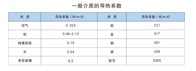
Thermal Conductivity
Thermal conductivity refers to the amount of heat transferred per second through an area of 1 square meter of a 1-meter-thick material under steady-state heat transfer conditions, with a temperature difference of 1 degree (K, °C) between the two surfaces. The unit is W/m-K (Watts/meter·degree). It is a physical quantity that describes the material's ability to conduct heat, a single inherent characteristic independent of the material's size or shape. For interface materials reinforced with glass fiber mesh or polymer films, however, their thermal conductivity depends on the relative thickness of different material layers and the direction of heat conduction. Therefore, it is more appropriate to use relative thermal conductivity to indicate the material's thermal performance.
Thermal Resistance
Thermal resistance represents the ability of a material with a unit area and unit thickness to resist the flow of heat, expressed as
Rθ=d/K……………………….(2)
For a single material, the thermal resistance is proportional to the thickness of the material. For non-single materials, the general trend is that the thermal resistance increases with the increase in thickness, but it is not a purely linear relationship.
Thermal conductivity and thermal resistance are used to describe the transfer of heat within a material after it enters. Because real surfaces are never truly flat or smooth, the contact surface between the surface and the material may also create resistance to heat flow. Actual products exhibit surface irregularities on a microscopic scale and surface distortions on a macroscopic scale, with actual contact occurring at high points. Air gaps will form in the recesses. Air gaps resist the flow of heat, forcing more heat to flow through the contact points, and this restrictive resistance is called surface contact resistance, which can occur on all mutually contacting surfaces.
Thermal Impedance
For interface materials, it is more appropriate to use thermal impedance under specific assembly conditions to indicate the level of thermal performance. Thermal impedance is defined as the sum of its thermal resistance and the contact thermal resistance of the contact surface, expressed as:
Zθ=d/(K.A)+Ri………………(3)
Surface flatness, surface roughness, clamping pressure, material thickness, and compression modulus will affect the contact thermal resistance, and these factors are related to the actual application conditions. Therefore, the thermal impedance of the interface material will also depend on the actual assembly conditions.
Factors Affecting Thermal Impedance
Contact area A: As the contact area increases, the assembly thermal resistance decreases.
Material thickness d: As the insulation thickness increases, the assembly thermal resistance of the material increases.
Assembly Pressure (Pressure): Under ideal conditions, as the assembly pressure increases, the thermal resistance decreases, but after the pressure increases to a certain value, the decrease in thermal resistance is very small. The pressure at this point is the optimal pressure value for the material. In addition, the magnitude of the assembly thermal resistance is also related to the testing method. Since these surface conditions may differ in different applications, the thermal impedance of the material will also vary with different applications.